Instead of doing something decent, such as studying for my exams today I decided to tinker around with a little wifi card that a friend of mine brought around a few weeks ago. Now this is a dangerous business, tinkering around with your computer like i do every week. You may end up burning your motherboard ( like i almost did), frying your CPU ( like i almost did), breaking you GPU ( guess what goes in this parenthesis), reseting some important CMOS or BIOS settings and oh so many many more things can go wrong, not because you don't know what you're doing but rather because things tend to go wrong. But if you're lucky and things DON'T go horribly wrong then you'll end up with something nice plus a feeling of achievement.
The wifi card in question is a AW-GA800BT usually found directly soldered onto Asus motherboards. But this was a standalone card. Its technical specs have a big 50 font, saying the card is based on USB 2.0 which is all fine and dandy if USB only had 5 wires instead of 4. But hey I completely ignored that...it wouldn't be the first time something worked with only half the wires plugged into it.
So I took an old USB cable, cut it to pieces and directly connected it to the board via the 4 circuits that it had on one corner and the big "USB" sign written next to them. Then connected it to the PC. Guess what ..well that didn't work. The next thing that I tried was to stick it into a USB port onto the motherboard via it's correct pins. Well that WOULD have worked if only USB had 5 wires instead of 4. The problem with it is that the card needed two power cables. The classic 5V usb one, plus another 3.3V that I don't have. I decided to take a old HD LED cable..because of it's easy connectors and cut it, connect it to the board and stick it onto another USB port's 5V wire. Originally I also added a diode thingy (that I took out of an old walkie-talkie) to drop the voltage from 5V down to 3.5 V. But for some reason when I redid the wiring the voltage went down to 2V which was less that I needed. So I took out the diode and used the 5V thing and luckily it didn't burn the card, it doesn't overheat and works just perfectly now.
To do all of this I had to use Google Translate , and translate this whole forum into English so I could understand something. Anyway thanks to everybody on the forum, and I really hope they don't mind I use their pics for explanatory reasons.

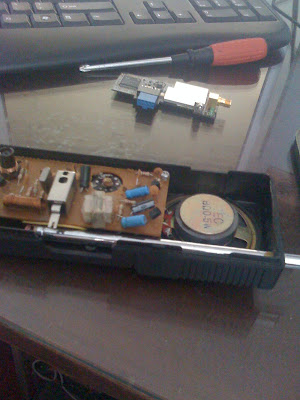
This is the old walkie-talkie and next to it is the card itself.

This is the card, and the old LED wire, connected to the 3V socket.
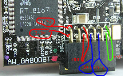
 "id="BLOGGER_PHOTO_ID_5324837743937859506" /> This is the wiring on the card, that's how you have to connect it. Original picture is found on the forum I mentioned above.
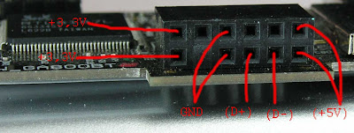
Again one more picture with the wiring

This is the end result, and I know it looks ghastly but it actually works perfectly it it's not that screwed up. You have one small cable that you connect on the motherboard to a 5V usb pin, and another wire that goes into any classical USB jack ( the kind in which you fit your flash drives)and that's it. Anyway hope this helps someone, it was quite fun to do. Cheers


24 comments:
Awesome.
Heyy man, ive got the same card and am trying to do the smae thing. would you mind posting a few pics of the wireing up close or contact me at wills_hot_account@hotmail.com
I also have the same card and tried to this on one of my computers, but I get a balloon message that states usb hub not recognized. So I put the driver on there, and still same message. So My wiring must be off. I am sure I did it right. But Some help would be nice. Contact me at jeff____b@hotmail.com (There are 4 underscores)
works like a charm. only problem i had was the chip on it gets very hot when i used the computers 5v power supply, even with a little heatsink on it. i put a variable pot on it and took it down to about 3.6v and it doesnt get as hot and works great. this link also helped.
http://pinouts.ru/Slots/USB_pinout.shtml
just great!! I just got a broken p5w-dh and was wondering if this could be done... but i have a question: when use the usb cable (the last pic), need to shot All D0+ D0- D1+ and D1-? is it in parallel? can you send me a e-mail? oton_jr@bol.com.br
sorry for my english, I'm brazillian
PS: You mind if I translate it and post on my blog? of course you will be mentioned as the original writer and a link to the original post on your blog will be placed.
Thanks for posting your experience
Interesting.
Has anyone tried the connection pins above the RTL-Chip?
They're labeled with 5V, D1-, D1+ and GND.
you need to switch D+ and D- wires..
how about soldering the 5v from usb cable also to both of the 3.3v?? it works for me, uses only one usb :)
To get ~ 3.3V put two 1n4148 diodes in series. Marvelous
thank so much
The card use only D0+ and D0- data wires.
D1+ and D1- goes directly to the USB EXT holes to be available second USB port.
3.3v you can get from ATX power connector orange wire.
Hey! I've used your guidelines to create the wifi to usb, just tested, works fine, i will be back with photos soon.
Here is the link to the photos with what i've built: it works, just tested.
Salut si mersi de comentarii. Uite articolul scris in romana. Apreciez daca postezi pozele si acolo http://rgstuff.ro/placa-wi-fi-aw-ga800bt/
Am pus si acolo... aici mi-ai sters tu linkul? :-)
Mersi iar pt docs, am luat placa cu 5 lei din targ. nu stiu insa daca merge reteaua ad-hoc, nu am cu ce testa momentan.
Acolo nu a aparut, iar aici nu am sters eu nimic e datorita spam filterului de blogspot probabil.
Using a connector that came with my new Asus board (M4A785G HTPC) and two 1n4148 diodes in series:
http://sidenius.net/stuff/azurewave_aw-ga800bt.jpg
Im not sure its a good idea to parallel two diodes. I may be wrong here. I think the thing to use here is a voltage regulator. Im looking into one now
This is similiar: http://vip.asus.com/forum/view.aspx?id=20091117193645875&board_id=1&model=P5B+Deluxe%2FWiFi-AP&page=1&SLanguage=en-us
No need to drop a diode just connect to 3.3v to orange color of atx 24 pins supply.
Maybe I'm lucky, but my module with the same exact model number has a J-tag type hole set right along the top of the card (considering the pinset that the author used to be along the "bottom" of the unit). In white-letter schematic style print it shows the correct pinout for the adjacent holes. 5V D+ D- Grnd NC NC So you can skip the 3.3V altogether. Four solder beads and 1 internal usb header cable later.... your done!
Thank you so much, this tutorial was very helpful. My media center/arcade computer now has Wi-Fi thanks to you! I knew it was a good idea to save this wireless module from my old Asus motherboard :)
I really like your content it is really very inspiring for I guess I have selected a mind blowing and interesting blog.suppercaubinhhp01
Post a Comment